Controller Diagrams
This section contains diagrams for the main PX4 controllers.
The diagrams use the standard PX4 notation (and each have an annotated legend).
Multicopter Position Controller
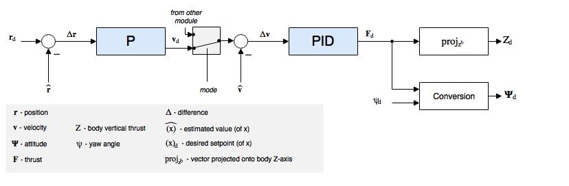
- Estimates come from EKF2.
- This is a standard cascaded position-velocity loop.
- Depending on the mode, the outer (position) loop is bypassed (shown as a multiplexer after the outer loop). The position loop is only used when holding position or when the requested velocity in an axis is null.
- The integrator in the inner loop (velocity) controller includes an anti-reset windup (ARW) using a clamping method.
Fixed-Wing Attitude Controller
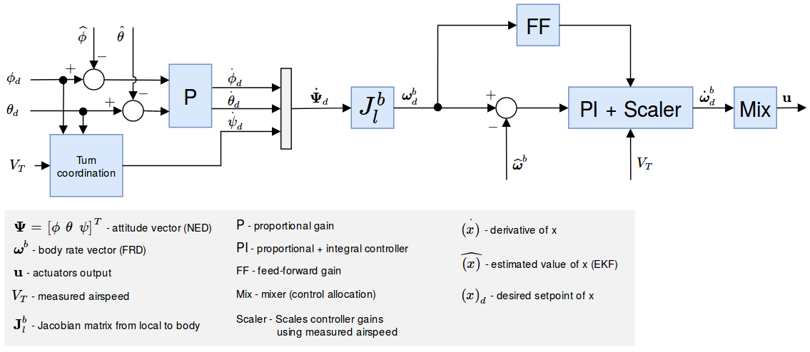
The attitude controller works using a cascaded loop method. The outer loop computes the error between the attitude setpoint and the estimated attitude that, multiplied by a gain (P controller), generates a rate setpoint. The inner loop then computes the error in rates and uses a PI (proportional + integral) controller to generate the desired angular acceleration.
The angular position of the control effectors (ailerons, elevators, rudders, ...) is then computed using this desired angular acceleration and a priori knowledge of the system through control allocation (also known as mixing). Furthermore, since the control surfaces are more effective at high speed and less effective at low speed, the controller - tuned for cruise speed - is scaled using the airspeed measurements (if such a sensor is used).
If no airspeed sensor is used then gain scheduling for the FW attitude controller is disabled (it's open loop); no correction is/can be made in TECS using airspeed feedback.
The feedforward gain is used to compensate for aerodynamic damping. Basically, the two main components of body-axis moments on an aircraft are produced by the control surfaces (ailerons, elevators, rudders, ... - producing the motion) and the aerodynamic damping (proportional to the body rates - counteracting the motion). In order to keep a constant rate, this damping can be compensated using feedforward in the rate loop.
The roll and pitch controllers have the same structure and the longitudinal and lateral dynamics are assumed to be uncoupled enough to work independently. The yaw controller, however, generates its yaw rate setpoint using the turn coordination constraint in order to minimize lateral acceleration, generated when the aircraft is slipping. The yaw rate controller also helps to counteract adverse yaw effects (https://youtu.be/sNV_SDDxuWk) and to damp the Dutch roll mode by providing extra directional damping.